
LM386 Audio Amplifier Board

The LM386 audio amplifier board is a compact and versatile integrated circuit widely used in low-voltage audio applications. Known for its simplicity and efficiency, it delivers reliable amplification for small speakers and audio projects. This popular chip operates on a voltage range of 4 to 12 volts, making it ideal for battery-powered devices. With built-in gain set between 20 and 200 through external components, the LM386 offers flexibility for various sound output requirements. Its minimal external parts requirement simplifies circuit design, appealing to hobbyists and engineers alike. Used in everything from portable radios to intercoms, the LM386 remains a staple in analog audio electronics.
Understanding the LM386 Audio Amplifier Board: A Compact Solution for Audio Projects
The LM386 Audio Amplifier Board is a widely used integrated circuit (IC) amplifier solution designed for low-voltage applications in consumer electronics and DIY audio projects. Known for its simplicity and versatility, the LM386 operates within a voltage range of 4V to 12V and delivers a variable gain from 20 to 200, depending on external components. It is commonly implemented in portable radios, intercoms, and small speakers due to its ability to amplify weak audio signals with minimal external parts. The amplifier board typically includes the LM386 IC, a few passive components (resistors, capacitors), and connectors for input, output, and power supply. Its low power consumption, ease of use, and compact design make it ideal for beginners and professionals alike who want to enhance audio signal quality without complex circuitry. Furthermore, the ability to directly drive a speaker—usually 8 Ohms—without requiring heat sinks adds to its appeal in space-constrained designs.
Key Features of the LM386 Audio Amplifier Board
The LM386 Audio Amplifier Board is celebrated for its minimal component requirements, which simplifies circuit design and reduces cost. It features low quiescent power drain, allowing it to operate efficiently in battery-powered devices. The amplifier provides adjustable voltage gain, typically set to 20 by default but can be increased to 200 using a capacitor and resistor between pins 1 and 8. It supports a wide supply voltage range (4V to 12V), making it compatible with various power sources. Other notable characteristics include built-in output short-circuit protection, high input impedance to prevent loading the source signal, and excellent ripple rejection for cleaner audio output. These features collectively make it an ideal choice for applications like small audio amplifiers, guitar pedals, and microphone boosters.
 Car Speaker System Installation Near Me
Typical Applications and Use Cases
The LM386 Audio Amplifier Board finds extensive use in both commercial and hobbyist applications due to its reliability and simplicity. In portable audio devices, such as handheld radios and mini boomboxes, it serves as a core amplification stage. It is also commonly used in electronic toys and musical greeting cards, where sound output is needed but space is limited. In the DIY and maker communities, the LM386 is a favored component for building low-power audio amplifiers, signal boosters, and active speaker projects. Additionally, it's frequently utilized in sensor interface circuits where analog audio signals from microphones or piezoelectric elements need amplification before processing. Its plug-and-play design and ability to function without complex tuning make it accessible even to those with minimal electronics experience.
Pin Configuration and Circuit Design Considerations
Proper understanding of the LM386’s pinout and internal architecture is crucial for effective circuit design. It comes in an 8-pin DIP (Dual Inline Package) with pin 2 (inverting input) and pin 3 (non-inverting input) serving as signal entry points. Pin 5 delivers the amplified output to the speaker, typically through a series capacitor. Pins 1 and 8 control the gain setting—leaving them unconnected results in a gain of 20, but adding a capacitor between them increases the gain to 200. Pin 6 is the positive supply voltage input, while pin 4 connects to ground. A bypass capacitor is usually placed between pin 7 and ground to stabilize internal biasing. Designers must also consider proper decoupling, input impedance matching, and minimizing noise pickup through careful PCB layout and grounding techniques to achieve optimal performance.
| Parameter | Typical Value | Remarks |
|---|---|---|
| Supply Voltage | 4V to 12V | Can go up to 15V for some variants |
| Quiescent Current | 4mA | Very low power consumption |
| Maximum Output Power | 0.7W | At 8Ω, 6V supply |
| Input Resistance | 50kΩ | High impedance minimizes loading |
| Gain Range | 20 to 200 | Adjustable via external RC network |
| Package Type | 8-pin DIP | Easy to mount on breadboard |
| Frequency Response | 300Hz to 10kHz | Suitable for voice and basic audio |
LM386 Audio Amplifier Board: A Comprehensive Guide to Setup and Applications
What issues commonly occur with LM386 audio amplifier circuits?

Instability and Oscillations
The LM386 is prone to instability, especially at higher gain settings or in poorly laid out circuits. This often manifests as high-frequency oscillations that are not audible but can cause overheating or distorted output. Stability issues typically arise from parasitic inductances and capacitances in the PCB layout or long wire connections in breadboard setups.
 Car Stereo And Speaker Installation
- Improper placement of the bypass capacitor (typically 10 µF) between pins 6 and ground can lead to oscillations; this capacitor should be placed as close as possible to the IC.
- Long input leads or unshielded wires can pick up RF interference, acting as antennas and feeding noise back into the amplifier, causing instability.
- The internal design of the LM386 lacks sufficient phase margin at high gains, especially when pins 1 and 8 are bridged with a capacitor to increase gain beyond 20, which can further destabilize the circuit without additional filtering.
Distortion and Poor Audio Quality
Users frequently report distorted or muffled sound, especially at higher volumes. This can stem from incorrect biasing, insufficient power supply decoupling, or inadequate output filtering. The LM386 has limited headroom and cannot deliver clean power into low-impedance loads without significant harmonic distortion.
- Operating the amplifier near or beyond its maximum output capability (e.g., driving 4Ω speakers instead of the recommended 8Ω) leads to clipping and high total harmonic distortion (THD).
- Absence or incorrect values of the output series capacitor and Zobel network (a resistor and capacitor in series from output to ground) can result in poor frequency response and distortion due to inductive speaker loads.
- Underpowered or noisy power supplies, especially when using batteries with high internal resistance, can modulate the supply voltage and cause audible distortion or buzzing.
Power Supply and Decoupling Problems
Inadequate power supply management is one of the most common sources of malfunction in LM386 circuits. Without proper decoupling, the amplifier can exhibit motorboating (low-frequency oscillations), increased noise, or intermittent operation. The LM386 is sensitive to supply rail fluctuations due to its high gain and limited power supply rejection.
- Missing or undersized supply decoupling capacitors, such as a 100 µF electrolytic in parallel with a 0.1 µF ceramic capacitor at the Vcc pin, allows noise and ripple to enter the amplifier stage.
- Using long power supply lines without local filtering introduces impedance that can interact with the amplifier’s dynamic current demands, leading to voltage dips and instability.
- Shared ground paths with other noisy components (e.g., microcontrollers or digital circuits) create ground loops, injecting noise through the common impedance and corrupting the audio signal.
What are the primary applications of the LM386 in audio amplifier board designs?
Portable Audio Devices and Battery-Powered Systems
The LM386 is widely used in portable audio devices due to its low power consumption and ability to operate efficiently on low-voltage supplies, typically ranging from 4V to 12V. This makes it ideal for battery-powered applications where power efficiency is crucial. Its compact design and minimal external component requirements allow engineers to integrate it into small form-factor devices without compromising audio performance.
- It is commonly found in portable radios, where its ability to drive small speakers with moderate output power (up to 1W) ensures clear sound reproduction in compact enclosures.
- Many battery-operated intercom systems and walkie-talkies use the LM386 to amplify voice signals without draining power quickly, extending operational time.
- In handheld audio recorders and voice memo devices, the LM386 amplifies microphone-level inputs to drive headphones or small speakers, offering a balance between simplicity and audio fidelity.
Interfacing with Microphones and Sensors
The LM386 is frequently employed to amplify weak audio signals from microphones, piezoelectric sensors, and other transducers in embedded audio systems. Its high input impedance minimizes loading on sensitive signal sources, and its internal gain-setting resistors allow for configurable amplification, typically from 20 to 200, depending on external components.
 Car Toys Speaker Install Cost
- In voice-activated switches and sound-detection modules, the LM386 amplifies microphone output so that microcontrollers can process the audio signals effectively for triggering actions.
- It is used in DIY electronic projects such as clapper circuits or sound-reactive LED displays, where ambient sound must be amplified before being analyzed or visualized.
- In educational kits and beginner electronics projects, the LM386 serves as an accessible way to demonstrate analog signal amplification from simple piezoelectric pickups or electret microphones.
Low-Cost Amplifier Solutions for Hobbyists and Prototyping
Due to its affordability, ease of use, and widespread availability, the LM386 is a go-to choice for hobbyists, students, and engineers during the prototyping phase of audio amplifier development. It requires only a few external components—such as capacitors and resistors—to function, reducing design complexity and assembly time.
- In Arduino and Raspberry Pi audio projects, the LM386 is often used to amplify PWM-generated audio signals, enabling the playback of tones or basic audio files through small speakers.
- It is commonly integrated into guitar practice amps and toy musical instruments, where cost-effective amplification is needed without requiring high-fidelity output.
- Many DIY audio filter and effects pedals use the LM386 as a final output stage to boost signal strength before sending it to a speaker or headphone jack, making it a versatile component in creative audio circuits.
What components are required to build an LM386 audio amplifier board?
Core Components for the LM386 Amplifier Circuit
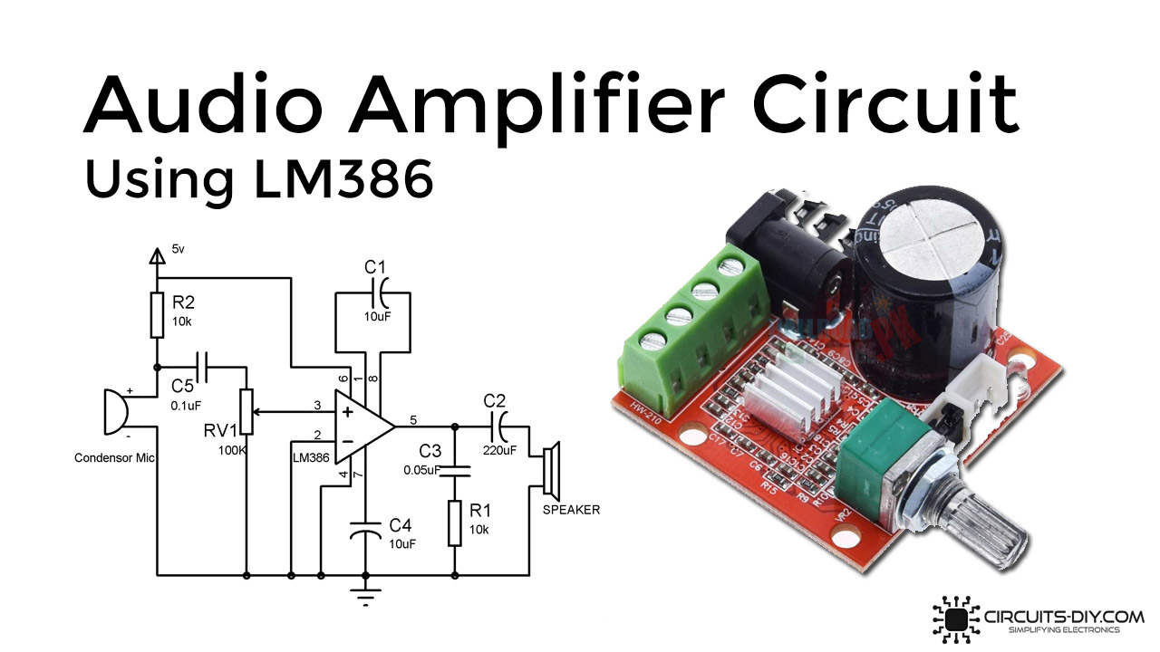
To construct a functional LM386 audio amplifier board, several core components are essential. The central part is the LM386 integrated circuit (IC), a low-voltage power amplifier specifically designed for battery-powered audio applications. This IC amplifies weak audio signals to a level suitable for driving small speakers. Alongside the LM386, a few passive components are necessary to ensure stable operation. A power supply, typically in the range of 4.5V to 12V, powers the circuit. Input and output coupling capacitors are used—usually a 10µF capacitor at the input and another at the output—to block DC voltage while allowing the audio signal to pass. A 10kΩ potentiometer is often included to control the volume by adjusting the signal level entering the amplifier. Finally, a small speaker (typically 4 to 8 ohms) is required to convert the amplified electrical signal back into sound.
- LM386 operational amplifier IC – the main amplifying component.
- 10µF electrolytic capacitors – for input and output signal coupling.
- Power supply source – 4.5V to 12V DC, such as a battery or adapter.
- 10kΩ potentiometer – for volume adjustment.
- 4 to 8 ohm speaker – for sound output.
Supporting Passive Components and Filters
In addition to the core parts, several supporting components stabilize the amplifier and improve audio quality. A 10µF capacitor is often connected across pins 1 and 8 of the LM386 to control the gain, increasing amplification from the default 20x to 200x when used. A 0.1µF ceramic capacitor is placed close to the power supply pin (pin 6) and ground to act as a bypass capacitor, filtering out high-frequency noise from the power source. A 10kΩ resistor in series with a 0.05µF capacitor can be added between the output and ground to create a Zobel network, which prevents high-frequency oscillations and improves stability. Additionally, a 220µF capacitor in series with the output helps block any DC offset from reaching the speaker, protecting it and improving sound clarity.
 Car Toys Speaker Installation
- 10µF capacitor between pins 1 and 8 – sets the amplifier gain to 200.
- 0.1µF ceramic capacitor – decouples the power supply and reduces noise.
- 220µF electrolytic capacitor – blocks DC from reaching the speaker.
- 10kΩ resistor and 0.05µF capacitor – form a Zobel network for stability.
- Additional ceramic or electrolytic capacitors – for power smoothing.
Board Layout and Connection Hardware
Building a reliable LM386 audio amplifier also requires consideration of physical assembly and connectivity. A perfboard or printed circuit board (PCB) provides a stable platform for mounting components and establishing consistent electrical connections. Male or female pin headers allow the board to interface with external signal sources, such as MP3 players or microcontrollers. Wires or jumper cables make connections between components, especially when using a breadboard for prototyping. A DC power jack may be included if a wall adapter is used instead of a battery. Switches can be added to control power flow, and heat shrink tubing or enclosures improve safety and durability. Proper placement of components, especially keeping input lines away from the output and power rails, helps minimize noise and feedback.
- Perfboard or custom PCB – for component mounting and circuit stability.
- Pin headers or connectors – for input signal and power connections.
- DC power jack or battery clip – for reliable power delivery.
- Jumper wires or pre-tinned cables – for internal and external wiring.
- On/off switch and protective enclosure – for usability and safety.
Frequently Asked Questions
What is an LM386 Audio Amplifier Board used for?
The LM386 Audio Amplifier Board is designed to amplify low-power audio signals, making them strong enough to drive small speakers or headphones. It's commonly used in portable audio devices, intercoms, radios, and DIY electronics projects. Its simplicity, low voltage operation, and minimal external components make it ideal for beginners and compact designs requiring moderate sound amplification with minimal power consumption.
How do I connect the LM386 amplifier to a speaker?
Connect the speaker to the output pin (usually pin 5) and ground through a 100µF capacitor to block DC voltage and protect the speaker. Ensure the amplifier's ground is shared with the audio source and power supply. Use a 6–12V power supply depending on your board version. Avoid exceeding the board’s power rating to prevent distortion or damage. For best results, use speakers rated between 4–32 ohms.
Can I adjust the volume on an LM386 amplifier board?
Yes, you can control volume by placing a potentiometer (e.g., 10kΩ) between the audio input source and the LM386’s input pin, acting as a voltage divider. This adjusts the signal level entering the amplifier. While the LM386 itself doesn’t have built-in volume control, adding an external potentiometer is a simple and effective way to manage loudness. Ensure wiring is secure to avoid noise or signal loss.
 Car Toys Speaker Installation Price
Why is my LM386 amplifier producing noise or distortion?
Noise or distortion can result from poor power supply quality, incorrect component values, or lack of decoupling capacitors. Use a stable 6–12V supply and add a 100µF capacitor between power and ground near the board. Ensure input connections are short and shielded. Ground loops, overloaded outputs, or impedance mismatch with the speaker can also cause issues. Double-check wiring and component placement for optimal performance.
Leave a Reply